

Microwave radio transmission is commonly used in point-to-point communication systems. One of the advantages of fixed wireless are the ability to connect with users in remote areas without the need for laying new cables and the capacity for broad bandwidth that is not impeded by fiber or cable capacities. Smallworld Radio Network Inventory solution, created in response to the growing use of wireless broadband by telecom operators, extends functionality of Smallworld PNI with enhanced modelling of radio towers and wireless equipment.
Smallworld Radio Network Inventory (RNI) supports point-to-point connections as well as broadcast devices. The signal coverage of the given device is calculated automatically based on object attributes. The tool also supports Radio Tower internals. RNI module allows Smallworld PNI users to keep data about radio equipment directly in PNI; it can also be integrated with LNI.
Supported business processes
- network planning
- connecting new customers to the network
- outage management
- network maintenance.
Radio objects in Smallworld PNI
RNI introduces new objects in Smallworld PNI:
- Radio Tower
- Radio Antenna
- Radio Connection
- Radio ODU (Outdoor Unit)
- Radio IDU (Indoor Unit) – as RME specialisation
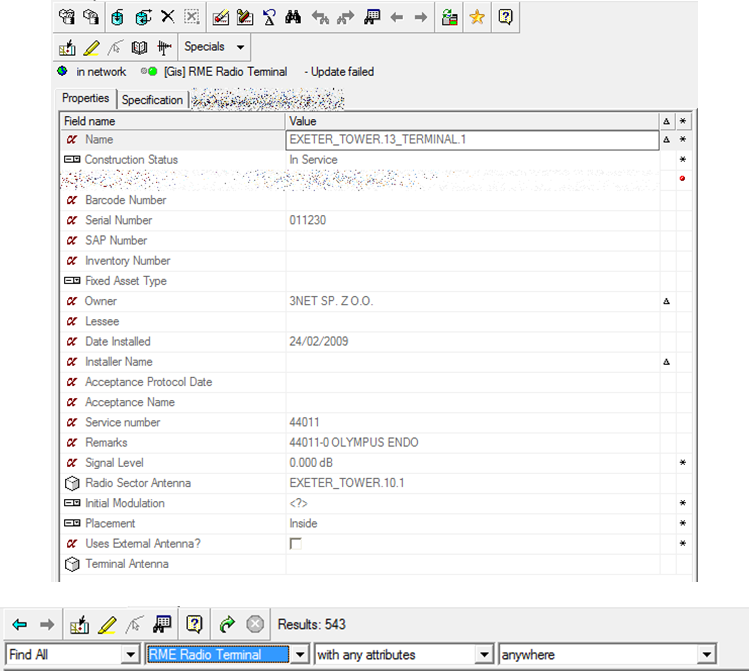
- RME Radio Terminal – as RME specialisation
The tool allows modeling objects and and its attributes in the following technologies: GSM, WiMAX, WiFi, SDH/SONET over Radio, Ethernet over Radio, LDMS etc.
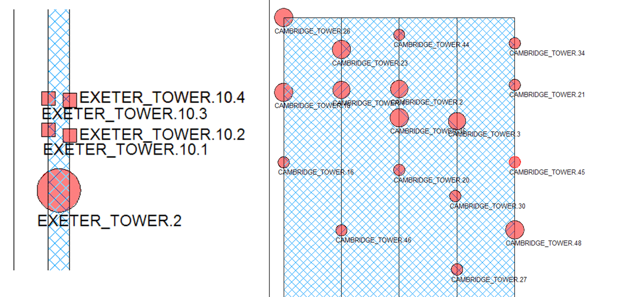
Radio Tower and Radio Antenna
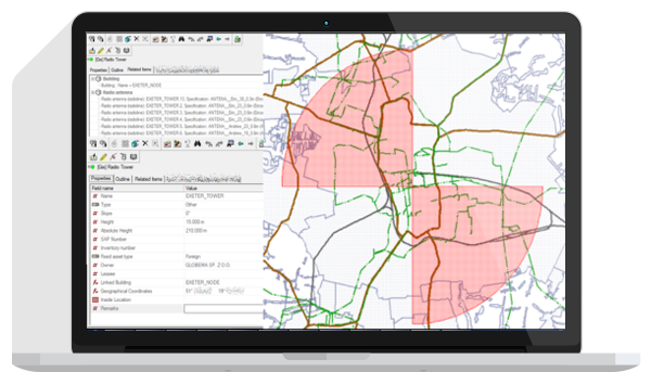
Radio Towers are located on the main map, and can be additionally placed in building internals. Radio Tower internals are created automatically based on tower shape attributes and are presented as tower geometric grid. There is also a simple wizard to determine tower shape. RNI introduces building roof geometry to indicate the exact location of the tower.
Radio antenna is placed on the tower; optionally it can be placed directly on the map. The shape is determined by antenna specification.
Radio antenna specification determines antenna type:
- Radioline (point-to-point connections)
- Sector (broadcasting point-to-multipoint transmission)
- Terminal (receiving point-to-multipoint transmission)
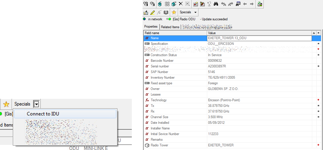
Radio ODU and IDU
The Outdoor Unit [ODU] is associated with radio antenna – it is created automatically while placing radio antenna. The Outdoor Unit is also connected with the Indoor Unit („ODU” port on RME radio device). The ODU has no geometry.
The Indoor Unit is a radio device (RME card or RME shelf) responsible for data transmission.
Radio Terminal
The Radio Terminal receives signal from p-mp (broadcasting) antenna. It can be free-standing or rack-mounted depending on specification. The terminal antenna can be built-in or external (placed on radio tower and connected with terminal in the same way as radioline or sector antenna is connected to IDU).
LNI Integration
The new version of RNI allows integration with the Logical Network Inventory. The network elements are mapped on Radio IDU Shelves/Cards and Radio Terminals. The physical path of facility representing radio connection is discovered automatically. LNI Structure tab visualises all services consuming radio link.
Learn more about LNIBenefits
- Modelling for wireless equipment within PNI – no need for external or customized solution
- Simple data model – efficient for everyday use
- Outage handling support